| PREVIOUS PRESENTATION | BACK TO PROGRAM OVERVIEW | NEXT PRESENTATION |
How accurate do you know your power at 300 GHz?
A. Steiger1, B. Röben1, K. Lange2, P. Mondal3, and P. Gellie3
1PTB Physikalisch-Technische Bundesanstalt, 10587 Berlin, Germany
2SLT Sensor- und Lasertechnik GmbH, 15745 Wildau, Germany
3Lytid SAS, 75013 Paris, France
So far, there is no metrology institute worldwide that can measure the power of a waveguide source in the WR-3 band with frequencies from 220 GHz to 330 GHz traceable to the International System of Units SI. PTB, Germany’s national metrology institute, has dedicated itself to this task in a Franco-German research project. The result is a new type of windowless detector that can measure the radiation emitted by an antenna directly behind its output (see figure 1). The calibration of the spectral power responsivity of each specimen will be possible as soon as the uncertainty budget is set up at PTB.
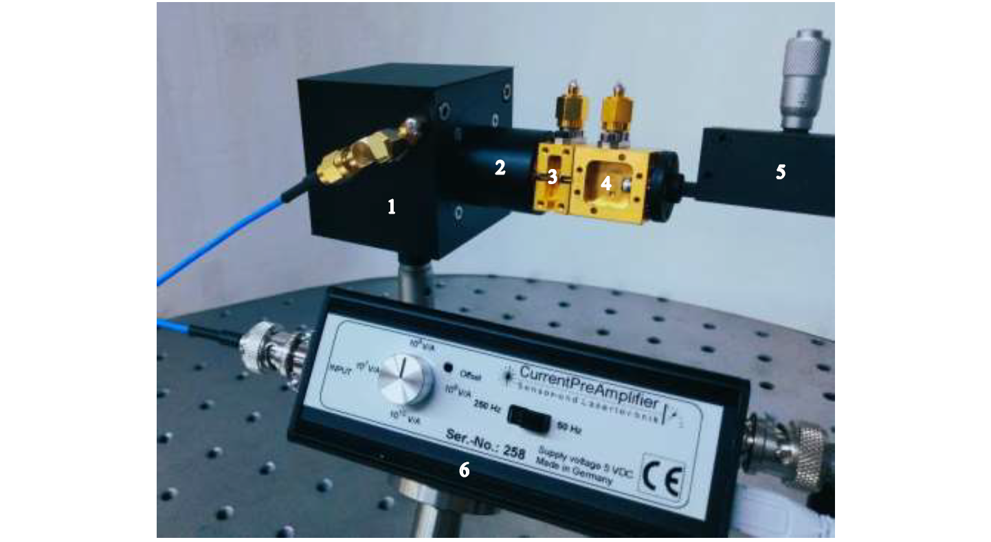
Figure 1: Photo of the prototype of SLT’s new detector (1), which is mounted directly in front of the output of a 300 GHz antenna. For precise positioning, the detector has an attachment adapted to the antenna, into which the antenna is inserted (2). Lytid’s frequency doubler stages for generating the 300 GHz from 150 GHz (3) and this from 75 GHz (4) are located at the waveguide input of the antenna. A waveguide-based power attenuator (5) can adjust the output power of an electronic source with a micrometer screw. The pyroelectric signal of the detector is amplified with an adapted current-to-voltage amplifier (6).
Problem
Power measurements in a rectangular hollow waveguide become increasingly difficult as the frequency increases because the dimensions of the waveguides become smaller and smaller. In the WR-3 band, which is important for upcoming 6G wireless communications, the transverse dimension is only three hundredths of an inch, which corresponds to less than 0.8 mm in metric units. These sub-millimeter dimensions hamper the installation of the complex sensor element, which comprises of a nonreflective absorber, a thermometer, and an electrical heater, inside the waveguide.
Solution
For this reason, we decided in our R&D cooperation project to determine the power directly at the output of an antenna. No imaging optics (mirror) are then necessary. The diverging emitted beam just behind the antenna is still small enough to capture the entire beam profile with the aperture of a large-area pyroelectric detector from SLT [1]. However, the specially coated thin-film absorbers of these pyroelectric detectors reflect 25 % of the incident power. If the reflection falls back into the antenna, not only is the measurement result distorted by interference (keyword: standing waves), but there is also a risk of destroying the frequency doublers of the electronic source or even the source itself. The solution is to tilt the detector by 45° from its normal position. The reflection is then at 90° to the beam axis. An absorber foam (ECCOSORB® AN-72) placed outside the divergent beam absorbs this reflection analogous to the absorption of the 25 % transmission behind the detector foil.
In addition, we had to clarify whether the placement of the conductive coated detector foil in the near field changes the emission of the antenna. For this purpose, the beam profile in the inclined detector plane was recorded point by point at PTB using 2D scanning. The measured distribution was compared with 3D simulations carried out by Lytid SAS of the radiated electric field of the antenna with and without the attached detector foil. The comparison showed good agreement between simulation and measurement. The result is that our detector layout does not noticeably change the antenna radiation and the antenna divergence is small enough to capture the entire beam profile even at 45° inclination with a detector of 30 mm diameter. A prototype of such a detector is the result of our R&D cooperation project (see figure 1) and was presented to an international audience of experts for the first time at the 11th Workshop on Terahertz Technology and Applications in Kaiserslautern on March 12, 2024.
All these outstanding properties create the prerequisites for determining the uncertainty budget of such a detector for its spectral power responsivity at 300 GHz when calibrated with PTB’s THz laser [2]. SLT will then be able to offer each new detector worldwide with an individual calibration certificate, as it is the case up to now for their free-space detectors. The specification of the measurement uncertainty ensures that a user can trust their own measurement with such a detector. This will make a vital contribution to closing the global metrological gap before new high-tech developments at 6G frequencies are launched on the market.
Acknowledgments
The results presented here were obtained in the Franco-German cooperation project called SCAFT (Secure communication at 6G frequencies through precise THz power measurements). The German participants were funded by the Central Innovation Program for SMEs (ZIM) of the Federal Ministry for Economic Affairs and Climate Action under the funding codes KK5104902AB0 and KK5114801AB0.
References
[1] A. Steiger, W. Bohmeyer, K. Lange, and R. Müller,”Novel pyroelectric detectors for accurate THz power measurements,” tm – Technisches Messen 83, 386-389 (2016); https://doi.org/10.1515/teme-2015-0083
[2] A. Steiger, M. Kehrt, Ch. Monte, and R. Müller, “Traceable terahertz power measurement from 1 THz to 5 THz,” Opt. Express 21, 14466-14473 (2013); https://doi.org/10.1364/OE.21.014466