| PREVIOUS PRESENTATION | BACK TO PROGRAM OVERVIEW | NEXT PRESENTATION |
Terahertz-wave dot projector for 3D imaging using a resonant-tunneling-diode oscillator
Adrian Dobroiu1, Yaqiong Li1, and Safumi Suzuki1
1Tokyo Institute of Technology, Japan
We report on the principle of a THz-wave 3D imaging system based on a dot projector and the initial experimental results. The 3D measurement technique is based on a geometrical principle: small dots are projected onto the target using a diffraction grating and an image of these dots is acquired form a different angle; the position of each dot in the image depends on the local depth of the target, which allows a 3D reconstruction of the target. The THz-wave source used in the experiments is a high-power resonant-tunneling-diode (RTD) oscillator array. In the current state, we were able to confirm that one dot’s position can be measured and the distance to the target can be calculated. The next step will be to perform the measurement for a larger number of dots.
Introduction
The RTD is a two-terminal semiconductor heterostructure typically composed of a quantum well sandwiched between two barriers. The I–V characteristic of the RTD includes a range of negative differential conductance (NDC), where the current decreases with increasing voltage. With a resonant circuit built around the RTD, by applying a bias voltage inside the NDC range, the circuit starts oscillating at a frequency determined by the inductances and capacitances in the circuit. By integrating an antenna in the circuit, the oscillation can be radiated into the free space as a terahertz wave. The advantages of RTD oscillators as THz sources are multiple: room-temperature operation, efficient conversion from DC to radiated power, small footprint, easy modulation in amplitude, tunability of the oscillation frequency, etc. RTD oscillators can also be used as THz-wave detectors. Increasingly higher output powers have been reported for single elements [1] as well as arrays [2], suggesting that RTD-based sources are ready for real-world applications. In our laboratory, besides fabricating our own RTD devices with various structures and functionalities, we actively pursue the development of applications for these devices, by investigating a number of techniques in radar [3], imaging [4], and communications. The research reported here is part of that effort.
Principle
The 3D technique presented here is inspired by the one used in smartphones for 3D face recognition and consists in projecting an array of THz dots on the target and recording an image of those dots from a different angle. The lateral position of each dot in the image depends on the axial distance to the target. For the configuration shown in Figure 1(a), if the surface of the target is farther away, the dot appears shifted more to the right. By measuring the shift of each dot in the image, the depth of the target at that point can be calculated; it is then possible to calculate the 3D shape of the whole target.
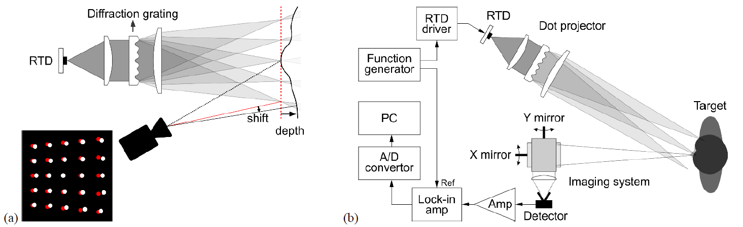
Figure 1: (a) Principle of measurement. Red dots and lines are for the case of a flat target. (b) Schematic of the experimental setup.
Figure 1(b) shows the experimental setup. The dot projector consists of an on-off modulated RTD source, a collimating lens, a diffraction grating, and a focusing lens. The diffraction grating is designed to split the incoming parallel beam into an array of parallel beams. The focusing lens projects those beams as dots on the target, which in turn scatters the incoming radiation.
For the imaging system we built a beam scanning setup based on two mirrors mounted on motorized rotation stages. A lens collects the beam reflected by the two mirrors and focuses it onto the terahertz detector, a waveguide-type Fermi-level-managed barrier diode (FMBD) equipped with a horn antenna. The detected signal is amplified and sent to a lock-in amplifier synchronized with the on-off signal that controls the RTD emission. The output of the lock-in amplifier is digitized and received by a computer, which also controls the rotation of the two mirrors, using a LabVIEW program.
Results
At the current stage in the experiments, we have designed the diffraction grating and had it manufactured, we have checked that it produces an array of dots, and we have built the experimental setup and confirmed that the relationship between the target distance and the dot position, for the case of a single dot, is what can be expected from geometry derivations. The diffraction grating was designed to generate a square array of 13×13 dots. The spacing between the dots was set at 20 mm for a focusing lens with a focal distance of 400 mm. This rather large spacing was set so as to obtain a clear separation between dots, whose diameter was calculated to produce a diffraction-limited spot size of about 7 mm. With a THz camera and a different setup, we were checked that the diffraction grating produces the array of dots as designed, with roughly equal intensities, although the camera lens only allowed us to view the central part of the diffraction pattern.
Without inserting the diffraction grating in the dot projector, only the central dot is obtained. We confirmed that this single strong dot projected onto a flat target is visible in the image, where its position was measured using a Gaussian fitting procedure. We then moved the flat target over a 60 mm range and found out that the dot moved as expected. Figure 2 shows an example of results. The dot position was found to be affected by an error of about 0.45 pixels (standard deviation); when the dot position is converted into target distance, the error of measuring that distance turns out to be around 3.6 mm (standard deviation).
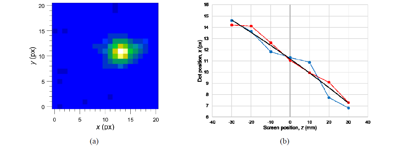
Figure 2: Experimental results. (a) Recorded image of one dot; in this particular image the center of the dot is approximately at x = 13.5 px. (b) The relationship between target distance z and dot position x, for two series of measurements (red and blue points), compared with theoretical results (solid black line).
Currently we are at the stage of switching from one dot to the full 13×13 array, by inserting the diffraction grating into the dot projector. However, when dividing the available power into this many dots, about half of the dots are obscured by noise. To overcome this limitation, we are considering several solutions, such as using a sensitive THz camera or replacing direct detection with heterodyne detection.
Acknowledgements
This study was supported by a scientific grant-in-aid (21H04552) from JSPS, CREST (JPMJCR21C4) from JST, X-NICS (JPJ011438), ARIM (JPMXP1223IT0014, JPMXP1223IT0015) from MEXT, SCOPE (JP215003005) from MIC, and commissioned research (JPJ012368C) from NICT, the ROHM Company, and the Canon Foundation.
References
[1] S. Endo and S. Suzuki, “Terahertz resonant-tunneling-diode oscillator with two offset-fed slot-ring antennas,” Appl. Phys. Express 17, 044001 (2024); doi: 10.35848/1882-0786/ad308b
[2] Koyama et al., “A high-power terahertz source over 10 mW at 0.45 THz using an active antenna array with integrated patch antennas and resonant-tunneling diodes,” IEEE Trans. THz Sci. Technol. 12, 510, (2022)
[3] J. Ito et al., “Real-time distance measurement using a subcarrier FMCW radar based on a terahertz-wave resonant-tunneling-diode oscillator,” IRMMW-THz (2021)
[4] A. Dobroiu et al., “Terahertz‑wave three‑dimensional imaging using a resonant‑tunneling‑diode oscillator,” Journal of Infrared, Millimeter, and Terahertz Waves 43, 464–478 (2022); doi: 10.1007/s10762-022-00863-5