| PREVIOUS PRESENTATION | BACK TO PROGRAM OVERVIEW | NEXT PRESENTATION |
THz-TDS detection of defects in ballistic inserts
Norbert Pałka, Kamil Kamiński, and Marcin Maciejewski
Military University of Technology, Kaliskiego 2, Warsaw, Poland
Ballistic inserts constitute a vital component of individual protective equipment utilized by military personnel and law enforcement entities. Over time, these inserts may manifest defects, delaminations, or moisture incursion, thereby compromising their efficacy. Consequently, it is imperative to subject them to rigorous testing to ascertain their continued operational integrity. The ballistic inserts under examination were manufactured as 25 x 30 cm plates contoured to conform to a segment of a circle with a radius of 40 cm (Figure 1). These plates comprised a 12 mm layer of high molecular weight polyethylene (UHMWPE), coupled with square ceramic plates measuring 10 mm in thickness and 50 mm in side length. The ceramic plates were composed of either aluminium oxide (Al2O3) or silicon carbide (SiC). To assess the capability for defect detection within the samples, specific defects were intentionally induced in the Al2O3-based sample: two 2 mm diameter holes drilled from the side into the UHMWPE layer and delamination at the interface between the UHMWPE and Al2O3 layers (see Figure 1b). Similarly, in the SiC-based sample, a delamination defect was introduced, extending halfway through the depth of the UHMWPE layer.
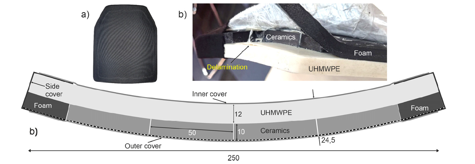
Figure 1: Ballistic insert: photo (a), PE and ceramic layer after removing the covers (b) and construction scheme (c).
For the time-domain spectroscopy (TDS) measurements, we utilized a reflection imaging scanner employing electronically controlled optical sampling (ECOPS) technology, specifically the TDS Toptica TeraFlash smart system equipped with a reflection THz head [1] (Figure 2a). This system facilitated the generation and detection of approximately 800 linearly polarized terahertz pulses per second, with a beam focal size of approximately 0.9 mm. The reflection THz head, comprising four off-axis parabolic mirrors, directed the THz radiation onto the sample surface at an incident angle of 8 degrees. To eliminate potential interference from water vapor, the head was purged with dry air. A part of the typical 400-ps long 10 times-averaged terahertz waveform, with a main pulse of 0.35 ps long (FWHM), reflected from a gold-plated flat reference mirror, is presented in Figure 2b. The spectrum of the THz pulse with a dynamic range of 35 dB and a 2.5 THz spectrum range is shown in the inset.
The mechanical configuration of the XY scanner comprised three motorized linear stages, each with a travel range of 750 mm, a maximum speed of 700 mm/s, a maximum thrust of 200 N, and a repeatability of 8 μm. Movement of the THz head was achieved point by point via a slow y-axis stage traversing over the aluminum breadboard. The aluminum breadboard, measuring 600 × 600 mm was uniformly displaced by two x-axis stages perpendicular to the y-axis stage’s movement direction. Setup for insert was a kind of extension for XY scanner (Figure 1). Its base was an aluminum plate measuring 60 by 60 cm placed on an optical table on four posts above the XY scanner. Two goniometric rails were mounted on the plate, the curvature of which corresponded to the curvature of the ballistic insert (40 cm). A pusher attached to the breadboard of XY scanner moved the insert along the rails, maintaining the perpendicularity of the surface and the scanning THz beam, as well as a constant distance between the head and the insert. The lowest point of the insert was located exactly on the focal point of the head. The rail elements were made by 3D printing from PLA material. The sample was measured with a pixel size of 1 x 1 mm2. The scanning time of one insert was approximately 17 minutes.
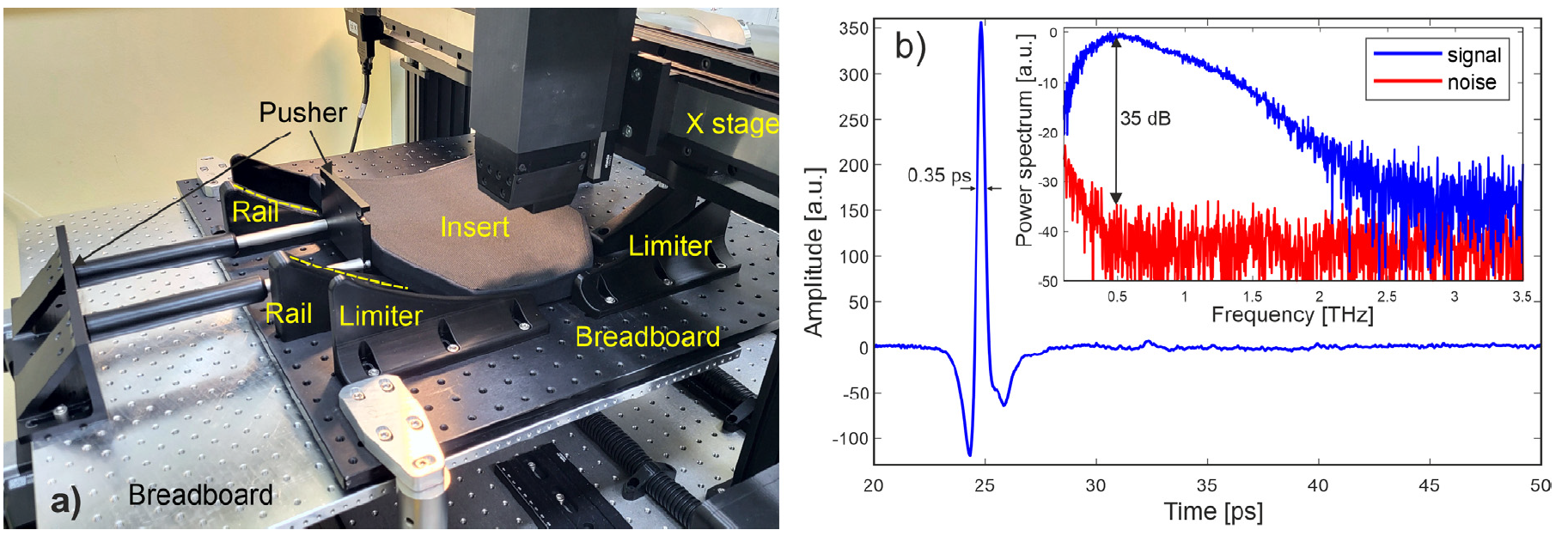
Figure 2: Scanner for testing ballistic inserts (a). Part of the 400-ps long THz waveform and its power spectrum in inset (b).
Figures 3 and 4 depict the C-scan in a a peak to peak in the slice mode, presenting detected defects in the samples based on Al2O3 and SiC, respectively. In the Al2O3-based sample, both holes and delaminations are observable. Additionally, at the interface between UHMWPE and Al2O3, a distinct pattern of the Al2O3 blocks is evident, alongside an area exhibiting increased reflection, possibly indicative of the presence of an air gap. This anomaly, not introduced deliberately, may signify a genuine defect. In the SiC-based sample, both the delamination and the pattern of the SiC blocks are readily discernible. The presented findings prove, that the THz-TDS technique can be used for non-destructive analysis of the ballistics inserts.
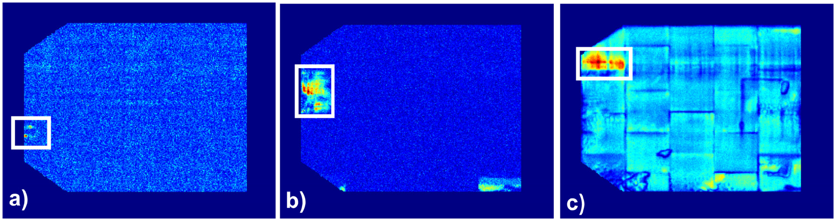
Figure 3: Defects detected in the sample based on Al2O3: holes (a), delamination in the UHMWPE (b), and regular pattern of Al2O3 blocks and the delamination at the interface between UHMWPE and Al2O3 (c).
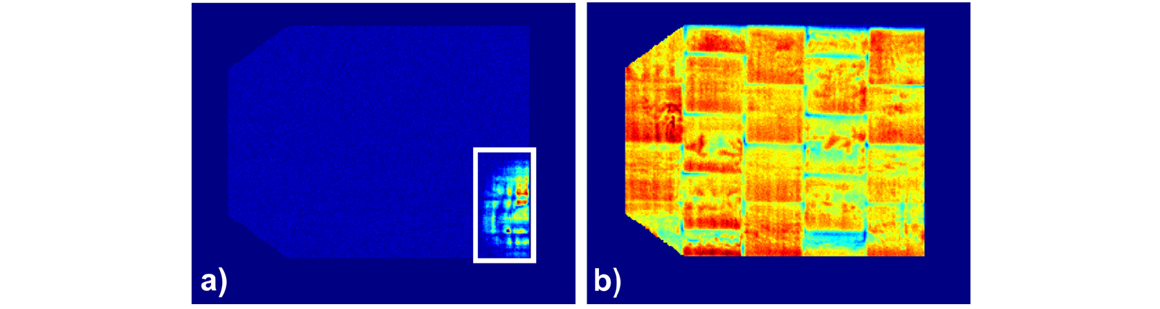
Figure 4: Sample based on SiC: delamination in the UHMWPE (b), regular pattern of SiC blocks at the interface between UHMWPE and SiC (b).
References
[1] N. Pałka, M. Maciejewski, K. Kamiński, M. Piszczek, P. Zagrajek, E. Czerwińska, M. Walczakowski, K. Dragan, P. Synaszko, W. Świderski, “Fast THz-TDS reflection imaging with ECOPS—point-by-point versus line-by-line scanning,” Sensors 22 (2022)